AFROBOT: Autonomous Drive Pet
AFROBOT is more than a class project, it’s the system I spent the most time thinking about, breaking, rebuilding, and refining.
Designed as an autonomous drive “pet,” AFROBOT follows a dark-green object using a Pixy2 vision sensor while continuously protecting itself from obstacles through infrared distance sensing. Under the hood, it combines analog signal conditioning, PWM motor control, and a subsumption-based behavior architecture that allows safety behaviors to override goal-driven motion in real time.
What makes this project special to me is not just that it worked, it’s how much time went into making it work. I spent months thinking through the architecture, behavior priorities, and circuit design long before final assembly, and even more time debugging real-world failures like wiring issues and damaged sensors near the deadline.
AFROBOT successfully demonstrated stable cruising, reliable obstacle detection at approximately 11 cm, and smooth object tracking up to one meter. Despite late-stage rebuilds and component replacements, the final system operated reliably and met all performance requirements.
This project also became the heart of this portfolio website. I revisited AFROBOT while designing this site, using it as a benchmark for how I want to present my engineering work: clearly, honestly, and with enough depth to show the thinking behind every decision.
The sections below walk through the system design, methods, challenges, and lessons learned from building AFROBOT.System Overview
- Power: A 7.2V NiMH battery regulated to 5V supplies both logic and motor control while maintaining electrical stability under load.
- Sensing: SSharp infrared distance sensors provide proximity feedback for obstacle avoidance, while a Pixy2 vision sensor outputs analog position data for object tracking.
- Control: An Adafruit Metro Mini microcontroller runs a non-blocking control loop that evaluates all behaviors continuously.
- Actuation: Dual DC motors driven through an H-bridge execute speed and direction commands derived from behavior arbitration.
- Behavior: Discrete components such as resistors, capacitors, and LM324 op-amps are used for signal conditioning, filtering, and amplification to ensure reliable sensor inputs.
AFROBOT was designed as a tightly integrated electromechanical system where sensing, control, and actuation continuously interact rather than operating in isolation. Every subsystem was chosen and tuned based on how it affected overall behavior and reliability.
Methods
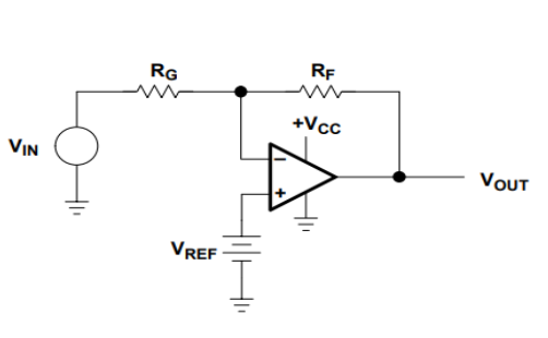
I- IR Sensor & Amplifier Circuit
The infrared distance sensors output a nonlinear voltage that varies with distance, which makes them unreliable if connected directly to the microcontroller. To address this, non-inverting LM324 op-amp circuits were used to amplify and stabilize the signals.
Each sensor outputs approximately 0.03 V to 3.1 V depending on distance. The amplifier gain was tuned so that obstacles at roughly 11 cm reliably crossed the escape threshold, enabling consistent obstacle avoidance behavior without false triggers.
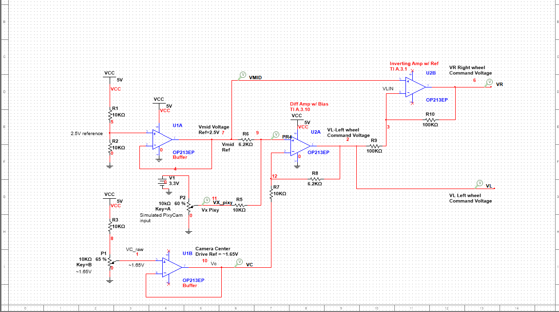
II- Pixy2 Tracking Circuit
The Pixy2 camera provides analog voltages representing the horizontal position of a tracked object. A differential amplifier converts this positional difference into steering corrections rather than absolute motor commands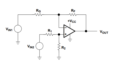
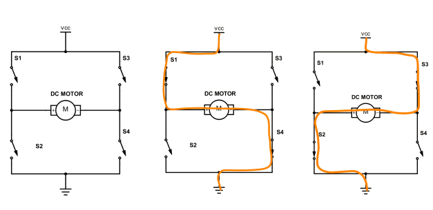
III- Motor Control & PWM
DC motors were driven through an H-bridge using PWM signals generated by the microcontroller. During testing, mechanical differences between motors caused noticeable drift, even under identical PWM commands.
Rather than treating this as a flaw, asymmetric PWM tuning was intentionally introduced to compensate for hardware imbalance a practical reminder that real systems rarely behave like ideal models.
.jpeg)
Subsumption Architecture
AFROBOT is controlled using a layered subsumption architecture in which multiple behaviors are evaluated continuously and executed based on priority rather than explicit state transitions. Each control loop independently processes sensor inputs and proposes motor commands, while higher-priority behaviors can override lower-priority outputs in real time. Reflexive safety behaviors such as emergency avoidance subsume goal-directed behaviors like object tracking and cruising, ensuring robust and responsive operation. The entire system is implemented using a non-blocking loop structure, allowing deterministic behavior arbitration and rapid response to environmental changes.
- Emergency: Highest priority – immediate safety
- Escape: priority – obstacle avoidance
- Track: Medium priority – follow green object
- Cruise: Lowest priority – forward motion
Control Code
AFROBOT’s behavior is implemented using a layered subsumption controller. Each behavior independently evaluates sensor inputs and proposes motor commands, while higher-priority behaviors override lower-priority ones in real time. The control loop is fully non-blocking and executes continuously.
Sensor Acquisition & Preprocessing
Analog and digital sensors are sampled every loop iteration. Pixy2 provides complementary analog voltages for object tracking, while the IR sensors provide proximity feedback for obstacle detection.
                    /// --- Sensor reads ---
                    int adcPixyL = analogRead(PIXY_LEFT_A);
                    int adcPixyR = analogRead(PIXY_RIGHT_A);
                    int adcIRL   = analogRead(IR_LEFT_A);
                    int adcIRR   = analogRead(IR_RIGHT_A);
                    bool pixyPresent = (digitalRead(PIXY_PRESENT_D) == HIGH);

                    // Convert ADC to voltage
                    float vPixyL = adcToVoltage(adcPixyL);
                    float vPixyR = adcToVoltage(adcPixyR);

                    float adcToVoltage(int adc) {
                      return ((float)adc / (float)ADC_MAX) * ADC_REF_V;
                    }
Emergency Behavior (Layer 4 — Safety Override)
The emergency layer overrides all other behaviors when both IR sensors detect a very close obstacle. A timed pivot maneuver is executed to rapidly disengage from the hazard.
                    // --- Emergency detection ---
                    if (!inEmergency) {
                      if (adcIRL >= IR_EMERGENCY_ADC && adcIRR >= IR_EMERGENCY_ADC) {
                        inEmergency = true;
                        emergencyStartTS = millis();
                      }
                    } else {
                      if ((millis() - emergencyStartTS) >= EMERGENCY_DURATION_MS) {
                        inEmergency = false;
                      }
                    }

                    // Emergency action: clockwise pivot
                    leftPWM  = clampPWM(BASE_SPEED + MAX_DELTA_ESCAPE);
                    rightPWM = clampPWM(0);
Escape Behavior (Layer 3 — Obstacle Avoidance)
The escape behavior activates when either infrared sensor exceeds the escape threshold. Differential steering is applied to turn away from obstacles, with a forced clockwise turn when both sensors are triggered.
                    bool leftEscape  = (adcIRL >= IR_ESCAPE_ADC);
                    bool rightEscape = (adcIRR >= IR_ESCAPE_ADC);

                    float nIRL = irNormalized(adcIRL);
                    float nIRR = irNormalized(adcIRR);

                    // Both sides blocked → force clockwise turn
                    if (leftEscape && rightEscape) {
                      leftPWM  = clampPWM(BASE_SPEED + MAX_DELTA_ESCAPE);
                      rightPWM = clampPWM(BASE_SPEED - MAX_DELTA_ESCAPE);
                    } else {
                      float turnNorm = (nIRR - nIRL);
                      float d = turnNorm * MAX_DELTA_ESCAPE;
                      leftPWM  = clampPWM(BASE_SPEED - d);
                      rightPWM = clampPWM(BASE_SPEED + d);
                    }
Track Behavior (Layer 2 — Object Tracking)
When an object is detected by the Pixy camera, symmetric speed control is used to center the object within the field of view. Wheel speeds are balanced around a base velocity to ensure smooth motion.
                  float pixyTurnNormalized(float vL, float vR) {
                    float diff = vR - vL;
                    float norm = diff / (2.0 * PIXY_HALF_SPAN);
                    return constrain(norm, -1.0, 1.0);
                  }

                  // Symmetric wheel control
                  float turnNorm = pixyTurnNormalized(vPixyL, vPixyR);
                  float d = turnNorm * MAX_DELTA_TRACK;
                  leftPWM  = clampPWM(BASE_SPEED - d);
                  rightPWM = clampPWM(BASE_SPEED + d);
Cruise Behavior (Layer 1 — Default Motion)
Cruise mode is the default behavior when no higher-priority conditions are active. Both motors are driven forward at a constant base speed.
                  leftPWM  = BASE_SPEED;
                  rightPWM = BASE_SPEED;
Motor Output & Mode Indicators
Final motor commands are applied through PWM outputs, and operating modes are communicated using a two-bit LED encoding scheme.
                void setMotorPWMs(int leftPWM, int rightPWM) {
                  analogWrite(PWM_LEFT_D, leftPWM);
                  analogWrite(PWM_RIGHT_D, rightPWM);
                }

                void setModeLEDs(Behavior b) {
                  digitalWrite(LED_MODE0_D, b & 0x01);
                  digitalWrite(LED_MODE1_D, b & 0x02);
                }
Full source code is available on GitHub. This section highlights the architectural logic and behavior arbitration strategy.
Results & Performance
AFROBOT was evaluated through a combination of bench testing and real-world navigation trials. Performance was measured not only by whether behaviors activated, but by how reliably and smoothly they transitioned during motion.
Obstacle Avoidance
Reliable IR-based detection with consistent avoidance behavior at approximately 11 cm.
| Distance | Output Voltage |
|---|---|
| >25-30 cm | ~ 0.03 V |
| 20cm | ~1.8 V |
| 15 cm | ~2.4 V |
| 11 cm (Trigger) | ~4.2 V |
The voltage increased nonlinearly, but the 11 cm point was consistent for triggering escape behavior.
Object Tracking
- Smooth Pixy-based tracking of a dark-green target up to a distance of 1 meter.
- Motor corrections were smooth and effective.
- Analog output was stable with minimal noise .
- Object remained centered within the field of view during motion.
Cruise Stability
- Stable forward motion achieved after PWM tuning and compensation for mechanical imbalance.
- Straight-line travel maintained over distances of several meters.
- Tracking behavior maintained the object centered most of the time.
- Escape behavior triggered consistently.
- All three behaviors worked simultaneously thanks to subsumption processing
Video Demonstration
The following video demonstrates AFROBOT transitioning between cruise, tracking, and escape behaviors in real time.
Engineering Challenges
The development of AfroBot presented several real-world engineering challenges that required troubleshooting, redesign, and iterative testing. These issues ultimately strengthened the reliability of the final system and demonstrated the importance of resilience in this project.
Wiring Failures & Full System Rebuild
Early testing revealed Late in the project, the primary control board experienced intermittent power loss caused by loose jumper connections and overused breadboard contacts. Symptoms included:
The system was rewired with shorter signal paths, improved strain relief, and cleaner separation between analog and digital subsystems. This significantly improved:
Lesson learned: Physical robustness is a core part of autonomous system reliability, and slow relearning of the wiring layout is a necessary trade-off for improved system stability.
IR Sensor Damage & Signal Protection
Multiple infrared distance sensors failed during prototyping due to wiring mistakes and insufficient electrical protection.
Faulty sensors were replaced and signal conditioning was redesigned using buffered inputs and controlled voltage ranges.
Lesson learned: Sensors are fragile dependencies and must be electrically protected.
Motor Drift & Mechanical Asymmetry
Despite identical PWM commands, the robot exhibited directional drift during straight-line motion due to mechanical differences between DC motors.
Asymmetric PWM tuning was implemented in software to compensate for hardware imbalance.
Lesson learned: Software compensation is often required for real-world hardware imperfections.
Behavior Priority Conflicts
Early implementations produced unstable behavior when tracking and avoidance routines attempted to control the motors simultaneously.
A strict subsumption hierarchy was enforced to ensure higher-priority safety behaviors always override goal-directed behaviors.
Lesson learned: Explicit behavior arbitration improves predictability and safety.
Future Work
While AFROBOT is a reactive system, it provides a strong foundation for more adaptive autonomy. Future development will focus on evolving the system from a purely reactive robot into a more adaptive autonomous platform.
- Introduce short-term state awareness to improve decision-making during repeated obstacle encounters.
- Expand emergency behaviors into multi-stage recovery routines that adapt based on obstacle persistence.
- Integrate distance sensing with visual tracking to improve perception robustness in cluttered environments.
- Add wheel encoders to enable closed-loop motor control and more accurate navigation.
Conclusion
AFROBOT demonstrates the successful integration of sensing, analog signal conditioning, and behavior-based control into a cohesive autonomous system. By leveraging a subsumption architecture, the robot achieves responsive, reliable operation while prioritizing safety-critical behaviors in dynamic environments. Beyond functional performance, this project emphasized real-world engineering challenges such as wiring robustness, hardware variability, and behavior arbitration — lessons that cannot be learned from simulation alone. More than anything, AFROBOT represents how I approach engineering: build, test, fail, fix, and iterate until the system works not just once, but reliably.